Connecting an RGB Display
This chapter will guide you on how to connect a 40-pin RGB display and refresh images to the framebuffer device to display them on the screen.
Introduction
Glossary
| Term | Explanation |
|---|---|
| fb | Frame Buffer |
| DPI | Display Parallel Interface |
| VOP | Video Output Processor |
| dtb | Device Tree Binary |
| dtbo | DTB Overlay |
| dtso | DTS Overlay |
- VOP is Rockchip's video output module, responsible for basic 2D graphics functions such as simple plane overlay, filling, cursor, and alpha blending.
Summary
There's a popular saying in our community: If it has a screen, the bad apple you shall code in it.
Young folks, why not try connecting a screen and see for yourself?
Choosing a Display Model
The Sakura Pi RK3308B features a 40-pin standard DPI interface.
The table below lists some tested displays that are compatible. You can choose one based on your needs. Since there are many types of displays, this list is for reference only. Generally, IPS panels offer better display quality than TFT panels.
Due to size limitations, the onboard backlight driver has limited power and may not support larger displays or those with high backlight power consumption.
If you encounter issues such as flickering or no display, consider using an external backlight power supply or switching to a different display.
| Model | Size | Approx. Price | Device Tree File |
|---|---|---|---|
| GL043056B0-40 | 4.3"@480x272 | 22CNY ~ 45CNY | [email protected] |
| RFH043X4024-01(EP4307) | 4.3"@480X272 | 20CNY | [email protected] |
| RFH043BIVI40A027-V2(EP4306) | 4.3"@480X272 | 25CNY | [email protected] |
| KD50G6-40TM-A1 | 5.0"@800x480 | 50CNY | [email protected] |
| MD050NL42-40-12A | 5.0"@800x480 | 60CNY | [email protected] |
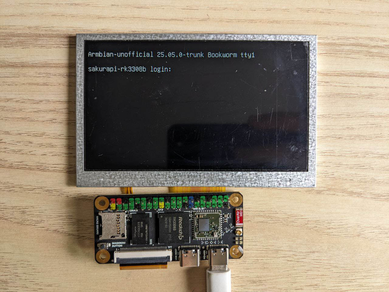
Powering On
Connect the display as shown in the diagram, plug in the power, and turn it on. By default, the display will light up automatically.
Display Detection and Resolution Adjustment
The default resolution in the device tree for the Sakura Pi RK3308B is 800x480. However, even if the resolution does not match, some displays can still work. For example, the "RFH043BIVI40A027-V2(EP4306)" can display images in a 480x272 area. For larger resolution displays, some may show abnormal images outside the 800x480 area.
Using a dtbo
The dtso is located in the Armbian mainline repository and is automatically compiled into dtbo and placed in the /boot/dtb/rockchip/overlay directory by default. Alternatively, you can download the appropriate dtbo for your display from the Choosing a Display Model section.
To configure and use the dtbo, add sakurapi-rk3308b-display@480x272 to the overlays line in /boot/armbianEnv.txt (if the line does not exist, add it). Replace the resolution with your display's resolution. If not supported, you will need to compile the dtbo yourself.
Writing a dtso for Your Display
If you need to customize a dtso, you can write it as follows for this development board. The compatible field corresponds to the display model. During the kernel driver probe process, the edt,etm0430g0dh6 field will be recognized and mapped to the parameters of the supported display in the module.
You can find all display models supported by the mainline kernel and reference parameters for similar displays in panel-simple.yaml.
/dts-v1/;
/plugin/;

/ {
    fragment@0 {
        target = <&display>;
        __overlay__ {
            compatible = "edt,etm0430g0dh6";
            status = "okay";
        };
    };
};
If your display is too advanced and not yet supported by the kernel, the situation becomes more complex. You will need to write it as follows. You may notice that the compatible field is set to panel-dpi. This is because panel-simple.c #L5217-L5218 has a fallback probe. When using this, you can freely write the parameters required for the display in the device tree, avoiding the need to edit kernel code.
The parsing of panel-timing is located at panel-simple.c #L435-L479.
/dts-v1/;
/plugin/;

/ {
    fragment@0 {
        target = <&display>;
        __overlay__ {
            compatible = "panel-dpi";
            status = "okay";

            panel-timing {
                clock-frequency = <25000000>; // in Hz
                hactive = <800>;
                vactive = <480>;
                hfront-porch = <8>;
                hback-porch = <8>;
                hsync-len = <4>;
                vfront-porch = <16>;
                vback-porch = <16>;
                vsync-len = <4>;

                hsync-active = <0>;   // 0: low active, 1: high active
                vsync-active = <0>;
                de-active = <1>;      // usually 1
                pixelclk-active = <1>; // corresponds to DISPLAY_FLAGS_PIXDATA_POSEDGE
            };
        };
    };
};
Writing Data to the Framebuffer
In the shell, you can write random data to the framebuffer using the following command:
cat /dev/random > /dev/fb0
In C, you can use mmap to map the framebuffer:
display_test.c
#include <fcntl.h>
#include <unistd.h>
#include <sys/mman.h>
#include <linux/fb.h>
#include <sys/ioctl.h>
#include <stdint.h>

int main() {
    int fb = open("/dev/fb0", O_RDWR);

    struct fb_var_screeninfo vinfo;
    struct fb_fix_screeninfo finfo;
    ioctl(fb, FBIOGET_VSCREENINFO, &vinfo);
    ioctl(fb, FBIOGET_FSCREENINFO, &finfo);

    int screensize = finfo.line_length * vinfo.yres;
    uint32_t *fbp = mmap(0, screensize, PROT_READ | PROT_WRITE, MAP_SHARED, fb, 0);

    for (int y = 0; y < vinfo.yres; y++) {
        for (int x = 0; x < vinfo.xres; x++) {
            int loc = y * (finfo.line_length / 4) + x;
            fbp[loc] = 0xFF0000FF;  // Red RGBA: R=255, G=0, B=0, A=255
        }
    }

    munmap(fbp, screensize);
    close(fb);
    return 0;
}